- Messages
- 232
After a few false starts(!) i'm now pleased to say that mine is fully working and fuss free!

There are 3 wires to connect:
RED: Coil +ve, or switched Live
BLUE: Coil -ve, or ECU Tacho out
BLACK: Ground
You just need to route the cables so that:
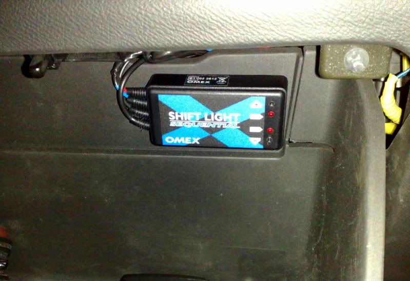
a) the control box is reachable when you turn the ignition key.
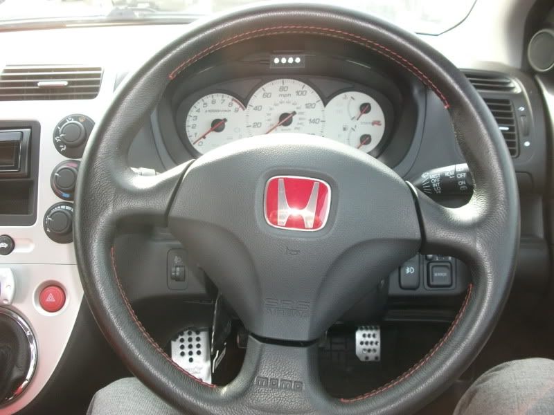
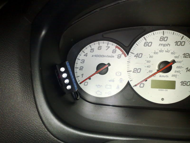
b) the LED module can reach the instrument binnacle. The module is about the size of an AA battery. Mine is sited at the 8 o'clock area, next to the Rev Counter. It is vertically attached using velcro, so that the LEDs illuminate upwards.
I originally planned to hard wire it into the spark plug loom, but that proved to be a bit of a guessing game.

So, I eventually found out from Hondata, that the ECU Tacho out (aka RPM signal) is the sole BLUE wire on the K20 ECU's "E" connector (the one on its own, out of the three connectors).
1) Disconnect the battery
2) Connect the BLACK wire to a suitable Grounding point on the chassis (the fixings are supplied)
3) Splice (or wire tap) the BLUE wire to the ECU Tacho out which is also BLUE
4) Splice the RED to a switched Live. I used the YELLOW wire behind the cigar lighter. Not the black! You may want to wire in an in-line fuse for your own peace of mind.
Set the Shift Lamp maximum RPM, and Lamp intervals as per the instructions supplied.
Put everything back together, reconnect the battery and all connectors, fire it up and VTEC away!

On my mechanically standard (for now) CTR, the settings are:
Max RPM shift point: 7800, allowing for my delay in shifting time
LED interval: 600
So, Green1 lights @ 6000, Green2 @ 6600, Amber @ 7200, Red @ 7800.
There are 3 wires to connect:
RED: Coil +ve, or switched Live
BLUE: Coil -ve, or ECU Tacho out
BLACK: Ground
You just need to route the cables so that:
a) the control box is reachable when you turn the ignition key.
b) the LED module can reach the instrument binnacle. The module is about the size of an AA battery. Mine is sited at the 8 o'clock area, next to the Rev Counter. It is vertically attached using velcro, so that the LEDs illuminate upwards.
I originally planned to hard wire it into the spark plug loom, but that proved to be a bit of a guessing game.
So, I eventually found out from Hondata, that the ECU Tacho out (aka RPM signal) is the sole BLUE wire on the K20 ECU's "E" connector (the one on its own, out of the three connectors).
1) Disconnect the battery
2) Connect the BLACK wire to a suitable Grounding point on the chassis (the fixings are supplied)
3) Splice (or wire tap) the BLUE wire to the ECU Tacho out which is also BLUE
4) Splice the RED to a switched Live. I used the YELLOW wire behind the cigar lighter. Not the black! You may want to wire in an in-line fuse for your own peace of mind.
Set the Shift Lamp maximum RPM, and Lamp intervals as per the instructions supplied.
Put everything back together, reconnect the battery and all connectors, fire it up and VTEC away!
On my mechanically standard (for now) CTR, the settings are:
Max RPM shift point: 7800, allowing for my delay in shifting time
LED interval: 600
So, Green1 lights @ 6000, Green2 @ 6600, Amber @ 7200, Red @ 7800.
Last edited by a moderator:
")